Wednesday, January 25, 2012

Some Reassembly

So firstly I need to apologize for the lack of photos here. When you have a friend over spending their time on helping you out, the last thing you wanna do is stop to take really detailed photos of everything because, well, it's their time too. So, I went through afterwards and tried to do my best to take good pictures of what we did.

So, to start where I left off on the other post, we reassembled the ink pump and capping station onto the frame. It's really easy, and it truly is the reverse of disassembly, everything just pops back into place and screws together.

My friend cleaned out the head area and really got it sparkling! You can see just how it came out!

Here's a closer picture of the pump/capping station, mounted up and attached to the frame.


Something else important is how the ink lines work with this replacement pump. The original lines had about 3 different types of hose and multiple (more than 3) connectors along the way. This new pump lets me simplify a lot. Mainly because the drain hoses coming from the unit are really long!

We cleaned out the thin tubing running to the ink tank and then I attached the hoses right into the silicone tubing, no connectors needed. These then feed directly into the waste ink tank. Here's how the hoses on my machine are currently routed. (I may need to change this, but not sure.)

Here's a shot of how my external lines are run. I may need to modify the large drain line, but the others should be alright. I know the holders are slotted to let you slip the line in and out, but they just destroy the hard plastic. If your lines are hard plastic, just pull them out of the waste tank and through the holes.
The spit cup has been cleaned out, and the important part: the drain line has been cleaned out as well. My friend spent a good 15 minutes squeezing huge long globs of solid ink out of the line. It looks like the large ink spill occurred due to an overflowing spit cup. There was at *least* 8 inches of solid ink in the line when we cleaned it. It's now clear, and hopefully will be routed in a fashion that promotes drainage. (once we figure out a way to attach it. The cup is still broken)
So, I went to install my new bulk cartridge into the printer, and found that it didn't go in! Well, I compared it to the cartridges that came with it, and found that the two little nibs on the top of the cartridge were to blame.

To properly install the cartridge into a Falcon 1, you have to cut off the nib shown on the left. The nib to the right stays.

After this, it went in fine.
The technique I used to clean the lines was the easiest that would (hopefully) get the job done. It involved filling my bulk ink tank with the cleaning solution that I made up, and then using the syringe I bought to draw the solvent through the lines, hopefully pulling all the old/dried/precipitated ink out of the lines and into my syringe, which I would then empty into the jar you see in the upper right.
In order to do this, I left the tip on the syringe hose, and slid it up onto the metal pipe, then pulled steadily and slowly on the syringe, to draw the solvent into the line. After about 20 seconds of vacuum on the line, solvent would pour through. It would take a couple syringefulls to get the solvent running clear.

You can see the lines on top are showing signs of being cleaned by the solvent.

It seems that some of the solvent drains back into the tank when the lines are disconnected from the syringe, or when there is not a constant vacuum pulling the ink into the lines. I'm curious if this will be the case when I attempt to print, or if the ink pump will take care of this. I'm not sure how much of a difference there is. Perhaps the dampers will help by providing a small reservoir of ink near the head, or a check valve.

I wanted to show a little more about some of the electronics inside the black box at the bottom. They look intimidating, but they really aren't that bad. Here we have the ink pump connector for the wires from the ink pump stepper motor. They go into the slot marked "INK PUMP" and it uses the same type of connector I showed previously on the control panel, the pull/push ZIF connector. Be gentle with it. The blue band on the wire and the small white arrow near the bottom of the connector indicate pin 1. Align these two when you are inserting the cable.

Here is the heater control connector, the large socket at the top. It is not a ZIF, so you will need to push the cable in as you did on the other side of the heater controller (shown in a previous post). Be careful, and make sure you match the silver side of the cable with the side containing the pins (also showed how to tell in a previous post).
The large black components with "CRYDOM" on them are solid state relays, which allow the unit to turn the 110VAC heater strips on and off to keep the temps up.
This is the socket for the control board. It is also a non-ZIF socket, so you'll need to carefully push the cable into the holder. It's the opposite direction from the heater cable, so make sure you pay attention to which side the pins are on!

Looks like someone at the factory forgot to pull the sticker off of the beeper after they washed the flux off!

Here's the head as it is currently. The O-rings and nuts have been removed, and the lines cleaned. I have let solvent rest in the lines to try and get it to break down more of the solidified ink, Magenta was the hardest to clean of all of them. It had grown quite thick and required a long time with constant suction to finally pull the solvent through. It's cleaned now though, and with the slow-drying properties of the solvent, leaving it in the lines should be good, even if it drains back.

I'm pretty forgetful, and in my excitement and rush to get this thing back together, I forgot about inks. Now, while the printer came with some, and they're somewhat full, they are over three years old. I'm not going to take the chance of messing up all the brand new stuff in here with some old ink, so I need to get some new ink. This was somewhat of a disappointment, as I had hoped I would get to start calibration and testing today, but alas, I'll need to wait for a bit so I can afford a new set of inks. Hopefully I'll pick them up the end of this month.

My plans are to run a bit more cleaning solution through each of the lines before installing the new inks, to clear anything else freed in the lines during the week-long soak. Then, I'll install the dampers and heads, and begin pulling inks through them. I'm investigating using only 4-color printing to save a bit, as I'll be buying the genuine inks.  Lots of questions about it on the forums, but no real 'how-to' style answers. I'll figure this one out and get something definitive put up about it.

For now, things are gonna go quiet for around a week while I relax and make money to pay for the rest of this.

Feel free to comment if you find this helpful or would like more info! I love feedback!

Monday, January 23, 2012

CMYKParts order

Well, the CMYKParts.com order just showed up, so here's my unboxing, to show everyone what you're getting when you buy the refurb kit.

Here's the box! (French on the box, it ships from Quebec)

Here's what's inside. Well-packaged, packed in peanuts, all the delicate parts wrapped in bubblewrap.

After getting rid of all the peanuts, the goods.

And finally, here's the parts themselves (of the refurb kit) after unpacking. I opened one of the heads, and they are packed in a pretty cool container, suspending the head in the middle of the box.
Head rank numbers are both printed on the box with a label, as well as written on the sides of the head in sharpie.
Here's a close-up of the new capping station. There are some differences here, mainly the larger rubber gasket around each pad, and the metal grate inside to prevent swollen pads from pressing against the nozzles and siphoning all the ink from the tanks. (A most terrible occurrence I've heard from the signs101 forums)

A comparison with the old capping station. Notice the old pads do not have any sort of grate to keep the sponges down, and the rubber on the new ones looks much better.

Here's the two pumps compared. Notice my old pump is missing the metal bracket holding the hoses in place. I'm not sure if that was originally there or it's a new feature added in later pumps.
Also, the ink lines supplied with the new pump do not have connectors halfway through them, so there's better path for the ink to flow.
The head itself. This looks shiny and new!

The backside of the head. It has identical markings to the DX2s I pulled out of the printer, so I won't post any comparison pictures here.

Just to add, here's the bulk ink container. I got this mainly so that I can feed solvent through the system, and it seems like it's constructed pretty well. It's solid, looks like it won't leak (hopefully) and it has some nice features on it. The piercing area is rubber, and the door at the top even has a little ring to pop it off for filling!

See?


Overall I have confidence with this kit. All the parts are new and clean, which is very nice after dealing with everything being covered in copious amounts of ink on the printer.

Also, if anyone is wondering how I've been taking these photos...

Sunday, January 22, 2012

Capping station and pump

This post is a how-to on replacing the capping station and pump. It's just a draft post for now, as I just did this and don't have it put back together yet, but I thought I'd post it up just so curious people can see what's up. This post will be edited tomorrow when the supplies come in.

I'm shrinking the images smaller on my posts to keep the scrolling down, as Blogger insists on having narrow post widths. As usual, click on any of them to get much larger shots.

I also picked up a cheap loupe ($14) from a local art store, for looking at the printouts to analyze dot placement. This is important for good head alignment, so I'll let you all know how it goes.

First, this is the capping station and pump assembly. Note the pump line routing, and how it connects to the station. This is important.

Notice that the tubes connecting to the capping station are curved to enter into the pump in a certain way. That's how we can tell which lines will be going to the capping station. The lines don't cross, they will be going to the pump on the same side of the capping station as they are on.

Here's another diagram where I've written in the way the lines run. (Capping Station is abbreviated) It's kind of complicated, but basically, both lines enter the pumps in the same way, and both exit the pumps. Both drain lines exit out of the back of the pump. The hose basically runs in a "U" inside the pump, with rollers using peristaltic action to pump the ink through the lines. While the pumps could run either direction, having one of them hooked up backwards would cause one nozzle to not be pumped out, making ink spill or keeping the nozzle from being properly cleaned.
The little bit I circled in green is a cut in the drain line. Ink was prolly pouring out here, so this is most likely the culprit for one of my ink leaks.


Remove the screw holding the capping station into the holder.

This will release the spring further and allow the capping station to be lifted out by the screw side. If you are only replacing the capping station, it may be wise to mark the hoses, but if you are replacing the pump as well, that won't help.

Disconnect the hoses from the now-freed capping station. Mark them if you aren't replacing the pump, if you are, make note of how the hoses are routed. Here's removing one...


And the other.


The capping station is now freed, and can be removed from the assembly.


Now that we have removed the capping station, we need to remove the pump. Here is a picture of the assembly with the capping station removed, for reference.

Start removing the pump by unscrewing the screw at the base of the bracket holding the pump to the main assembly.

To remove the gears holding the pump in place, you also need to remove the two screws on the outside of the pump housing to allow the gear plate to come off.

The gear plate is removed. The small gears are attached, the long shafts are freed.

Now that the long drive shaft has been removed, we can remove the pump.

Friday, January 20, 2012

Quick Cleaning

Well, I was bored, and having just mixed up that solvent, I decided to give it a whirl and try cleaning up the electronics box cover. That thing has a huge mess of ink on it. Well, it did. Here's some pix:

This is the 'before' pic. A little cleanup I did on the side for the previous demo pictures, but otherwise, just how it was. The ink blotches there are actually caked ink.. it's been dripping down there for some time. Looks like since the last service was botched.

My method for cleaning it is something I should mention, since I was trying to NOT use 800 paper towels. I basically dabbed a liberal amount of the solvent onto the ink blob, and let it soak in to soften/dissolve the ink. I then used the paper towel to scrape off as much of the bulk ink as I could, and repeated. It only took a couple passes on each large blob. Afterwards, I went over it with a solvent-dampened clean one, and that finished things off.

The 'after' shot. This is after I got all that gunk off. The ink seems to have done something to the metal coating, as I was not able to affect the blotches there. The little warning sticker was doing okay at first, but the overlaminate gave in to the solvent, as it had already been badly damaged by the ink. Only the backing (minus the printing) is there.


All in all, it was a great test. The solvent did a wonderful job of cleaning up the ink from rough metal even, and I'm looking forward to using it for cleaning the lines and whatnot as well.

Solvents

So, I got the tracking number for my refurb kit today. It ships out of Canada, Quebec, to be precise. It's on the way, and scheduled to be here Monday, and since that's my day off, I'll be here with my friend to work on it. There will be a huge post and lots of info!

So, to kinda get ready, I decided to start mixing up some of the solvent mix that I've seen on the forums, to see if it really works. Here's what I did:

I started with a normal quart tin purchased from Lowe's. I was worried about the enamel finish inside would be affected by the solvents, but it appears that it is not, but that's from a short period of time. I'm going to let it hang out in here til Monday and see how it's affected.

By the way, red Solo cups are polystyrene, and they don't like Acetone!

Usually, the mix is mentioned as being 4 or 5 parts Butyl Carbitol to one part Acetone. I mixed at 5 to 1.

I mixed 2.5 cups Butyl Carbitol to 0.5 cups Acetone. Poured them into the tin together and stirred. Mixed it is a clear liquid; the Butyl Carbitol is a more viscous liquid, like a light oil, and the Acetone is very watery, be careful when pouring it.

I then tried it out on the electronics lid, which looked pretty nasty. It worked spectacularly.
Here's the lid, after a little cleaning, as a before picture.

This is after about three seconds of rubbing with a corner of the paper towel dipped in the solvent.

And the after, as you can see that whole area rubbed is just clean beneath. I didn't do a whole lot more, I'll wait a little to work on that, but it really works well on the dried ink. I even used it on an old, very dry ink spill, and it came right up, no problems. I'm excited for how this should work on the insides of the printer.

Wednesday, January 18, 2012

Ribbon cables

So I since I've been idle for a few days, I thought I should write a little more here, take some shots, and show off what I'm working on.

I set up my little studio here so I can get some good shots of the work I'm doing.

Basically, I found someone (Atlantic Computer Service) who had the ribbon cables for cheaper than other places online. I bought a pair of them there (used, of course) yesterday, and because they're in Seminole, FL, I got them today!

I ordered "The Big One", aka the refurb kit for my printer from CMYKParts.com. Hopefully it'll get here soon. I also ordered a bulk ink tank (to fill with cleaning solvent), and a syringe kit with tubing to help work the solvents through the system.

So what I need to do today is explain more about ZIF FFC (Zero Insertion Force Flat Flexible Cable) connectors and cables, and show how to replace them in the printer. The ones I bought also had ink on them, but just a little bit here and there, so nothing as bad as the ones that came out of my printer. The important thing is that the plastic covering is in great shape and they ohm out properly (I'll show more about how to do that later on as well)

So, 
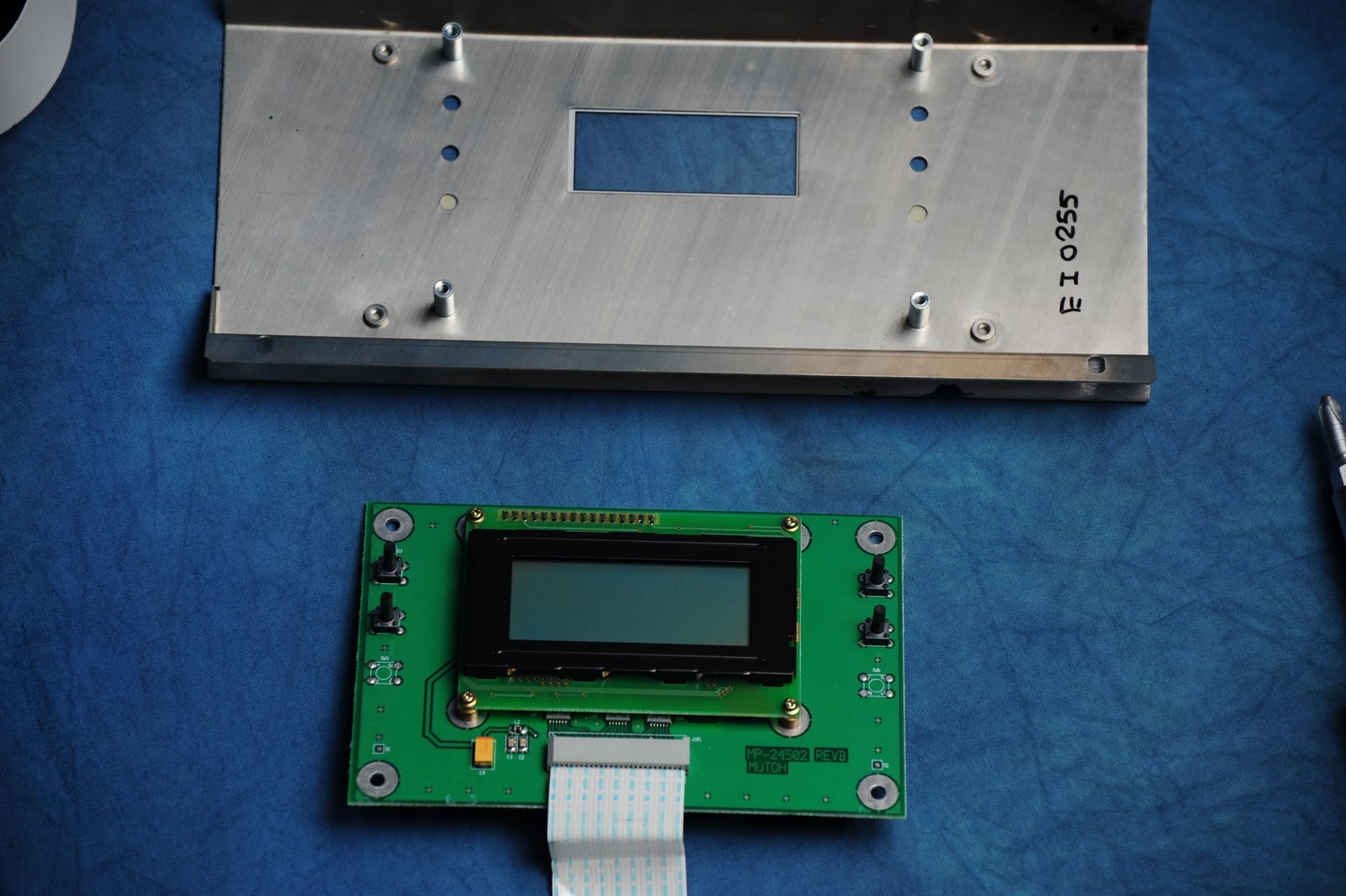
first we'll start with the heater control panel, as it's pretty important. First, you need to remove it from the printer with the two screws on top. This is pretty easy. After that, disconnect the cable from the electronics box and pull it out (carefully) through the holes it's routed through.

Now that you have it outside the printer, we can work on it. First, we flip it over onto it's face. I've 
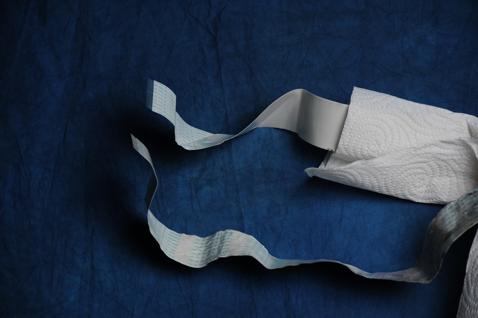
covered some of the old cable with paper towel cause I don't want the copious amounts of ink on it to mess up my backdrop.


First, you'll need to remove the two screws holding the ribbon cable to the metal. They have attached washers.


 Then, remove the metal plate and place it aside (It's a good idea to keep the screws with the plate so you know where they go when you reassemble!)


Now, remove the four outer screws holding the gold plate down to the silver face.


These have washers that are NOT attached, so don't lose them!
Flip the cable over to the other side of the panel, and remove the gold plate from the front panel assembly.

Now, remove the four screws holding the circuit board down. They are the large ones on the outside corners. They may be in tight, so make sure you use an appropriately-sized screwdriver so you don't strip them, and press down on the screw while turning! These screws are longer than the other two types of screws, so it shouldn't be hard to keep them separate.


Then, lift the board up and out of the front panel. You'll notice the long pushbuttons, be sure not to bump them around too much.
The ZIF socket for the cable on this board is a press-in type, so there is no lever or slide to move. It relies on the rigidity of the cable, fitting much like an old NES or GameBoy cartridge would, it slides against pins on the inside.


To remove it, carefully pull straight back, wiggling it very slightly side to side. You will see it slowly move outwards until it pops free. Don't bend it very far to either side or you risk bending pins inside or breaking off the cable within the connector.

The cable and board are separated. Now to install the new cables.

You can see here, that the old cable (paper towel) matches the curves of this used cable. This is how I'll determine which end and which cable to use here.

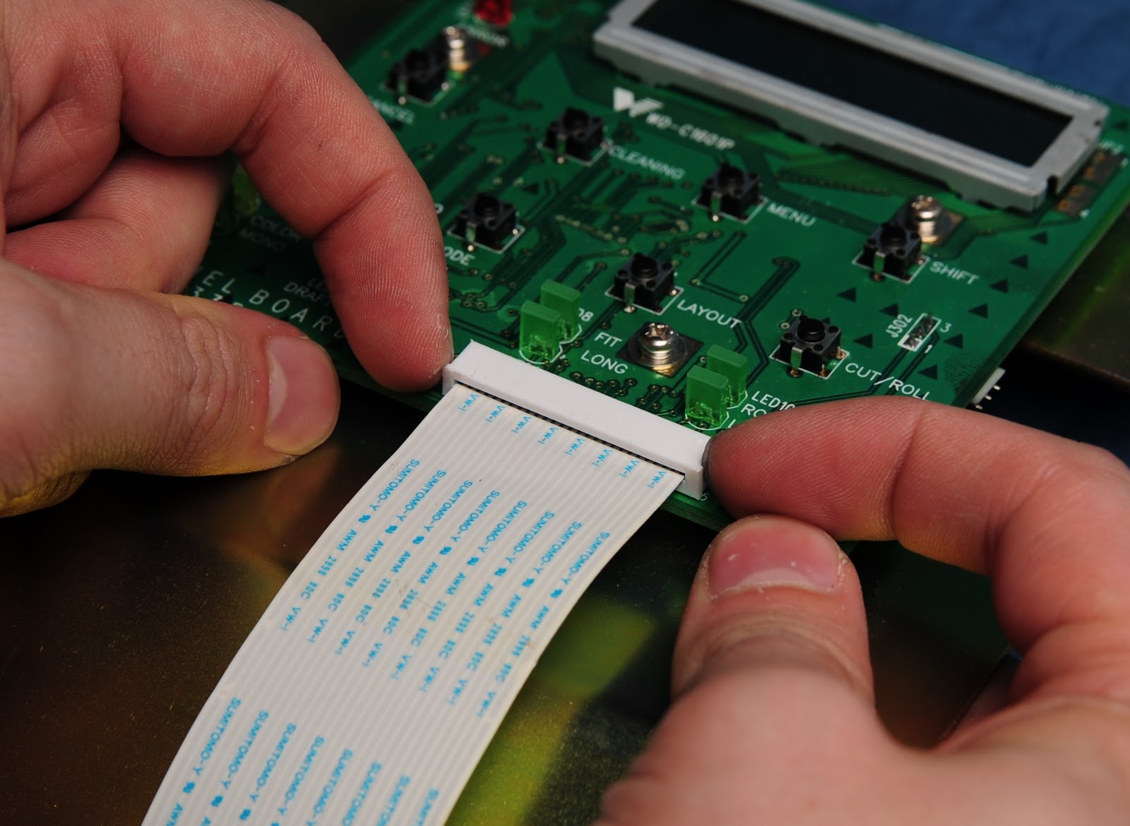
First, look into the end of the connector. You will see a side with pins, and a side without. The side with pins is where the silvery side of the cable goes. The blue side (stabilizer tape side) goes down, in this case.

Position your thumb very close to the connector; this is to ensure the cable does not buckle as you insert it. Gently slide the tip of the cable into the slot, and while doing so, keep the cable pressed against the board to keep it rigid. Wiggle it back and forth slightly while applying even pressure inwards.

The cable will start to slide in with some resistance, then the resistance will suddenly drop and it should slip in all the way. Ensure it's fully seated (without buckling the cable) and you're done!


Now, to reassemble the rest of the panel, we do the above in reverse. Place the LCD face-down onto the front panel, align the holes, and install the four long screws. Ensure the long buttons are seated properly in the holes before tightening the screws.

Then comes the gold plate. Fit it on with the angled side fitting against the large angled piece on the silver front panel, and install the four screws with washers.

Last, fold the ribbon cable back over the panel, and install the strain relief bracket. make sure there's a bit of slack in the cable, so that it's not rubbing against the sharp edge of the gold plate.

Now, in my instance, I didn't really need to replace the heater cable. In fact, the one that came was kinda beat up, moreso than the one I had. After washing the cable under some hot water (keeping the ends dry) and paper towel, I found that the cable itself seemed to be in good condition, and the only one with an issue was the main control panel cable. I did this purely for the tutorial and photos, and to see what was inside.


Next up, we have the main control panel. I'm going to show this one as well, because it's using a different socket, and there's a lot less disassembly required.

This is the control panel removed from the unit. It's cable follows the same path as the heater control panel, only it attaches to a different point in the electronics box.

To remove the cable, first you need to release the cable strain relief. This is done by loosening the screw on the strain relief. You don't need to fully remove it, loosening it up is plenty to remove the thin cable.

This is the ZIF connector we are dealing with. It is the locking/unlocking type, which you can tell by noting the two shells, and the ridge about the bottom shell which is to provide an area to grip when sliding it.

After the strain relief has been loosened, you need to unlock the ZIF connector BEFORE you pull out the cable. If you don't, the pressure against the pins inside can damage the cable AND the pins within. To release it, use your fingernails (or fingers) to GENTLY pull the large outer shell with the ridge downward.

You may wiggle it slightly, after it loosens up it will slide to the bottom and stop, looking like the photo to the right. Do not pull it past this or you will break the connector!

Now, carefully pull the ribbon cable straight out with both hands, and it should slide easily free. Note the orientation on the cable, as it is more difficult to see inside these connectors to find the pins. The orientation on this panel is with the silver side of the cable facing away from the board.

Replacement is easy as well. Simply slide the cable into the slot and push it gently to the rear of the connector (until it stops). If it does not slide in, make sure the little latch is down all the way (don't pull it hard, it just sometimes slips upwards a little)

Then, using two fingers, push straight up on the ridged shell until it stops, which will lock the cable in place.

When you are done, it will look like this.

Re-tighten the cable strain relief (make sure you leave a little slack) and you are done!