I set up my little studio here so I can get some good shots of the work I'm doing.
Basically, I found someone (Atlantic Computer Service) who had the ribbon cables for cheaper than other places online. I bought a pair of them there (used, of course) yesterday, and because they're in Seminole, FL, I got them today!
I ordered "The Big One", aka the refurb kit for my printer from CMYKParts.com. Hopefully it'll get here soon. I also ordered a bulk ink tank (to fill with cleaning solvent), and a syringe kit with tubing to help work the solvents through the system.
So what I need to do today is explain more about ZIF FFC (Zero Insertion Force Flat Flexible Cable) connectors and cables, and show how to replace them in the printer. The ones I bought also had ink on them, but just a little bit here and there, so nothing as bad as the ones that came out of my printer. The important thing is that the plastic covering is in great shape and they ohm out properly (I'll show more about how to do that later on as well)
So, first we'll start with the heater control panel, as it's pretty important. First, you need to remove it from the printer with the two screws on top. This is pretty easy. After that, disconnect the cable from the electronics box and pull it out (carefully) through the holes it's routed through.


Then, remove the metal plate and place it aside (It's a good idea to keep the screws with the plate so you know where they go when you reassemble!)

 These have washers that are NOT attached, so don't lose them!

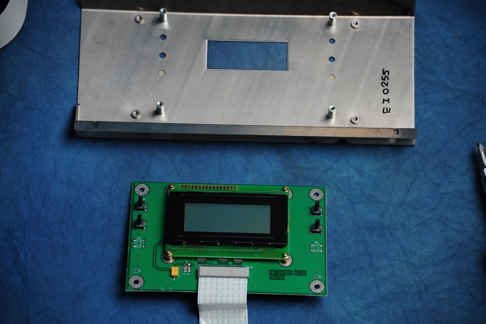 Now,
remove the four screws holding the circuit board down. They are the
large ones on the outside corners. They may be in tight, so make sure
you use an appropriately-sized screwdriver so you don't strip them, and
press down on the screw while turning! These screws are longer than the
other two types of screws, so it shouldn't be hard to keep them separate.
Now,
remove the four screws holding the circuit board down. They are the
large ones on the outside corners. They may be in tight, so make sure
you use an appropriately-sized screwdriver so you don't strip them, and
press down on the screw while turning! These screws are longer than the
other two types of screws, so it shouldn't be hard to keep them separate.Then, lift the board up and out of the front panel. You'll notice the long pushbuttons, be sure not to bump them around too much.

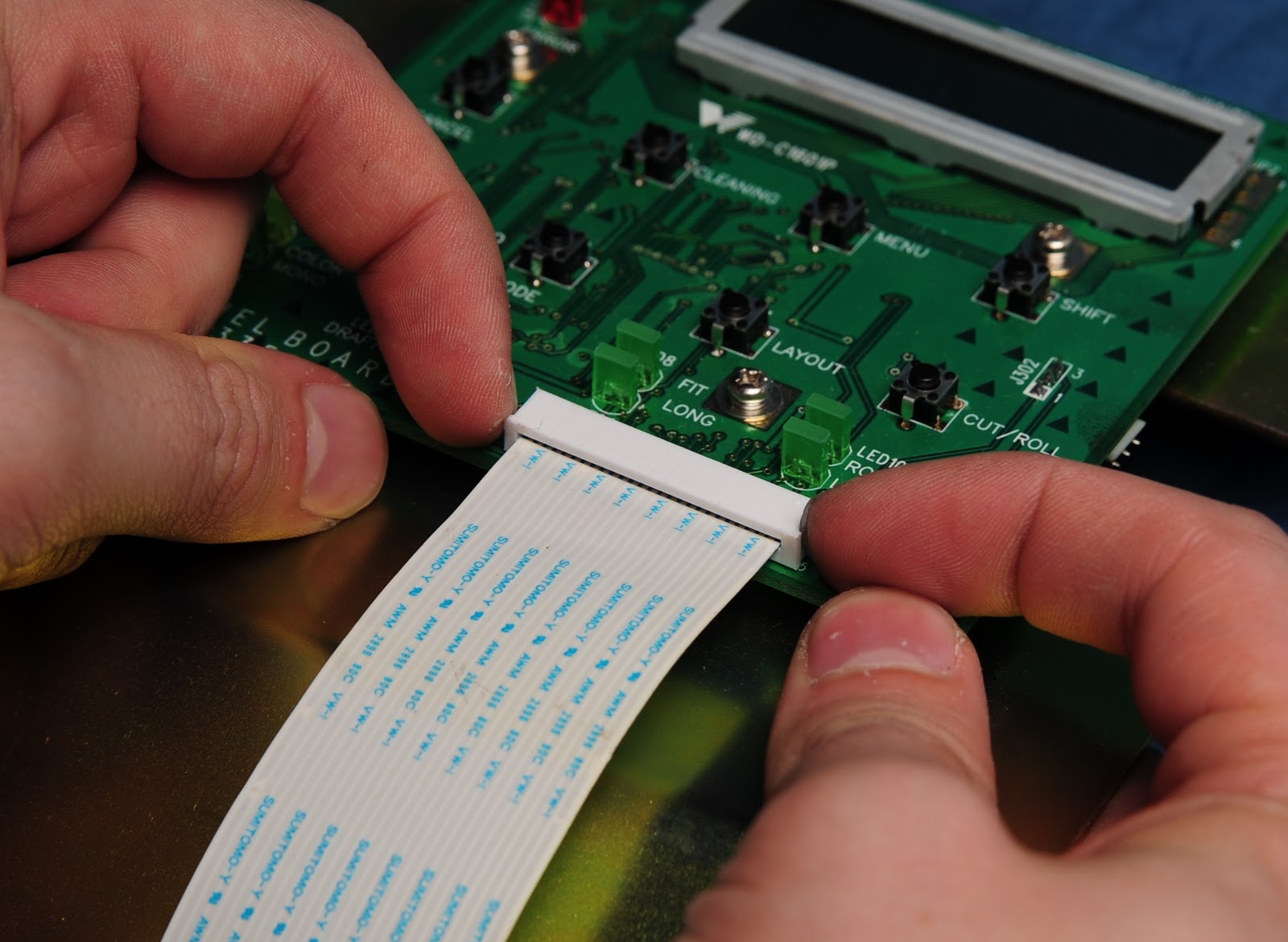
 The ZIF socket for the cable on this board is a press-in type, so there is no lever or slide to move. It relies on the rigidity of the cable, fitting much like an old NES or GameBoy cartridge would, it slides against pins on the inside.
To remove it, carefully pull straight back, wiggling it very slightly side to side. You will see it slowly move outwards until it pops free. Don't bend it very far to either side or you risk bending pins inside or breaking off the cable within the connector.


Now, to reassemble the rest of the panel, we do the above in reverse. Place the LCD face-down onto the front panel, align the holes, and install the four long screws. Ensure the long buttons are seated properly in the holes before tightening the screws.
Then comes the gold plate. Fit it on with the angled side fitting against the large angled piece on the silver front panel, and install the four screws with washers.
Last, fold the ribbon cable back over the panel, and install the strain relief bracket. make sure there's a bit of slack in the cable, so that it's not rubbing against the sharp edge of the gold plate.
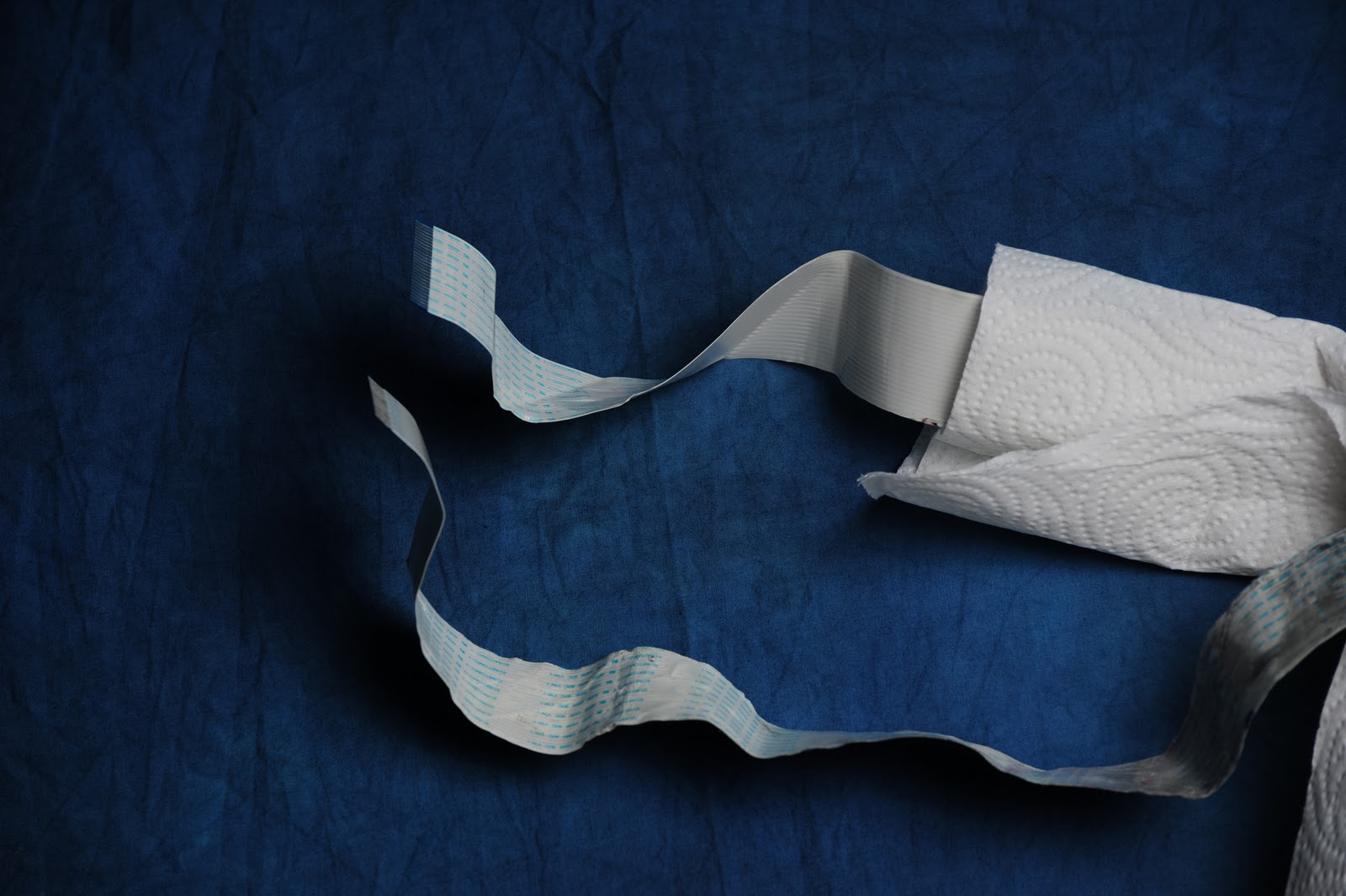
Now, in my instance, I didn't really need to replace the heater cable. In fact, the one that came was kinda beat up, moreso than the one I had. After washing the cable under some hot water (keeping the ends dry) and paper towel, I found that the cable itself seemed to be in good condition, and the only one with an issue was the main control panel cable. I did this purely for the tutorial and photos, and to see what was inside.

This is the control panel removed from the unit. It's cable follows the same path as the heater control panel, only it attaches to a different point in the electronics box.


Re-tighten the cable strain relief (make sure you leave a little slack) and you are done!
No comments:
Post a Comment