Alright, so here we go, going to start diving into this thing. It seems a bit daunting, but I'm going to go at it and see where we can get.
A friend is interested in using this printer with me, so she's offered to help with some costs and work involved in getting it back up and running again. It's just the drive I need to work on it, so she came over and we proceeded to tear down the printer to see just what I'm going to need to get this thing up and running again.
While I don't have any in-depth pictures of the teardown, it's pretty straightforward. Everything is held in with screws that can be easily found, so nothing too hard there. Here's a few pictures, and comments on disassembly:
Starting out, this is the left side of the printer. The cover is removed with two screws at the bottom of the cover. You can see the metal band idler to drive the head, and the belt to drive the grit roller.
This is the right side of the printer. Here you can see the lever to raise/lower the upper pinch rollers, the large DC motor to drive the steel belt, the hoses routing to the waste ink bucket, and at the top, the switch to enable/disable the printer based on the lid position. If your printer keep saying to close the lid, or allows printing when the lid is open (or you want it to), adjust the switch mount until it engages properly.
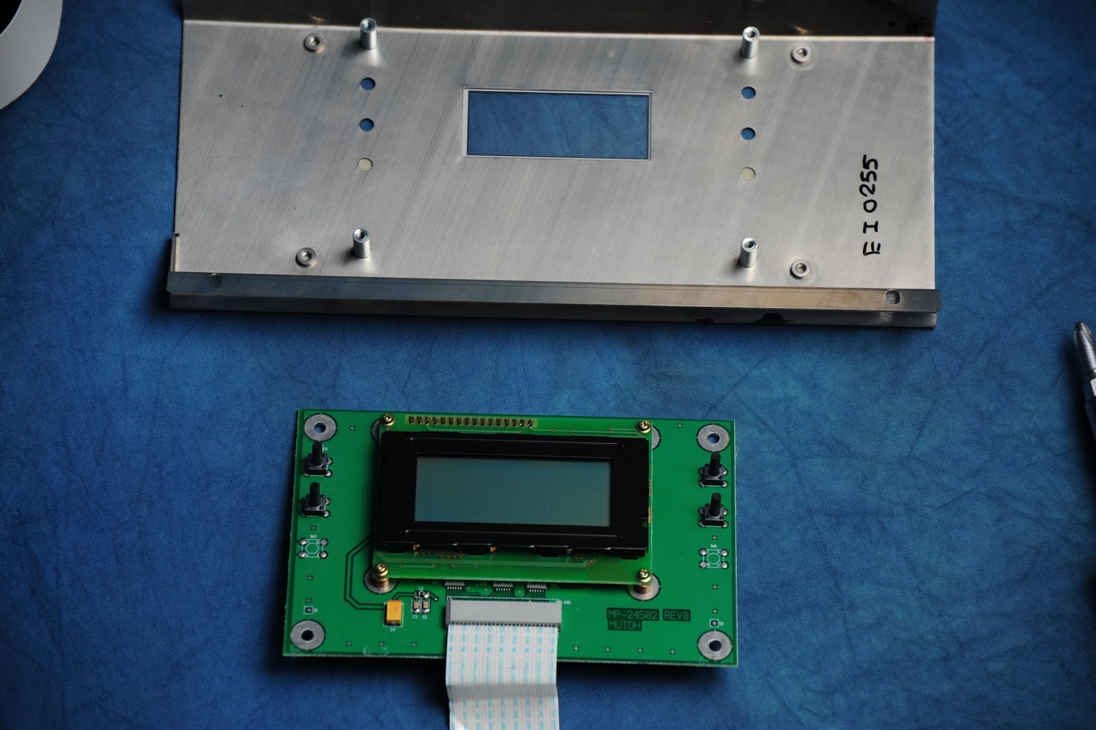
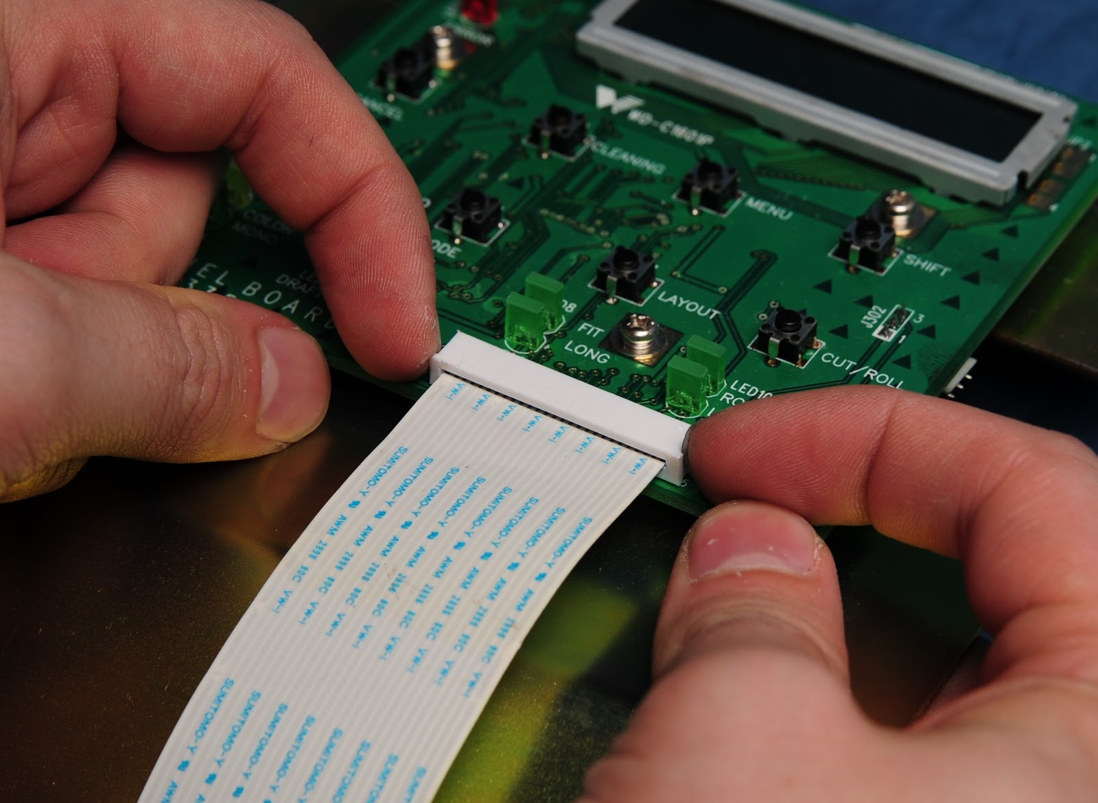
This is the front panel area, with the cover removed. In this shot, We also removed the front lid, which you can see is missing. The front cover is removed with one screw near the top left of the control panel; the rest of the metal panel needs to be unscrewed from beneath the heater controller to come out. The ribbon cables are standard ribbon connectors; they have plastic pieces that slide downward slightly to release the cable from the connector. Don't try to remove the plastic piece completely or do anything else than slide it up and down, it will break.

As you can see here, the front panel and heater board have been removed. This allows us to see the ink pump (black object to the left), the capping station (two pads on top) and the waste ink hoses (white/clear hose leaving to the right). The white hoses are from the ink pump, and the clear large hose is from the spit cup. A word of caution about removing the spit cup: While it is made of solvent-resistant plastic, the piece which it is attached to is not. In my case, this ended up with me removing the small supports that hold the cup in place, as they had been damaged by misdirected printer ink. I will need to come up with another way to affix this. (pictures soon)
Another shot of the control panel area. You can see where the control panel was affixed, as well as where ink splattered/dripped from something being improperly aligned. The hole near the center of the picture which goes down into the electronics enclosure, is covered in ink. This caused the following problem.
Just to the left of this (behind the black plastic piece we removed along with the spit cup) is a foam filter used to clean air going into the vacuum fan area. This was also soaked in ink, so we removed it. We are going to try and locate some high density foam to replace it with, by tracing the old shape and cutting it out of new foam.
As you can see, the ribbon cable coming from the heater assembly, going down into the electronics enclosure is covered in ink. This is a problem, because the plastic on the ribbon cable is not solvent resistant. While it does not appear to have attacked the cable in this instance too badly, I have not cleaned it yet to check the damage.
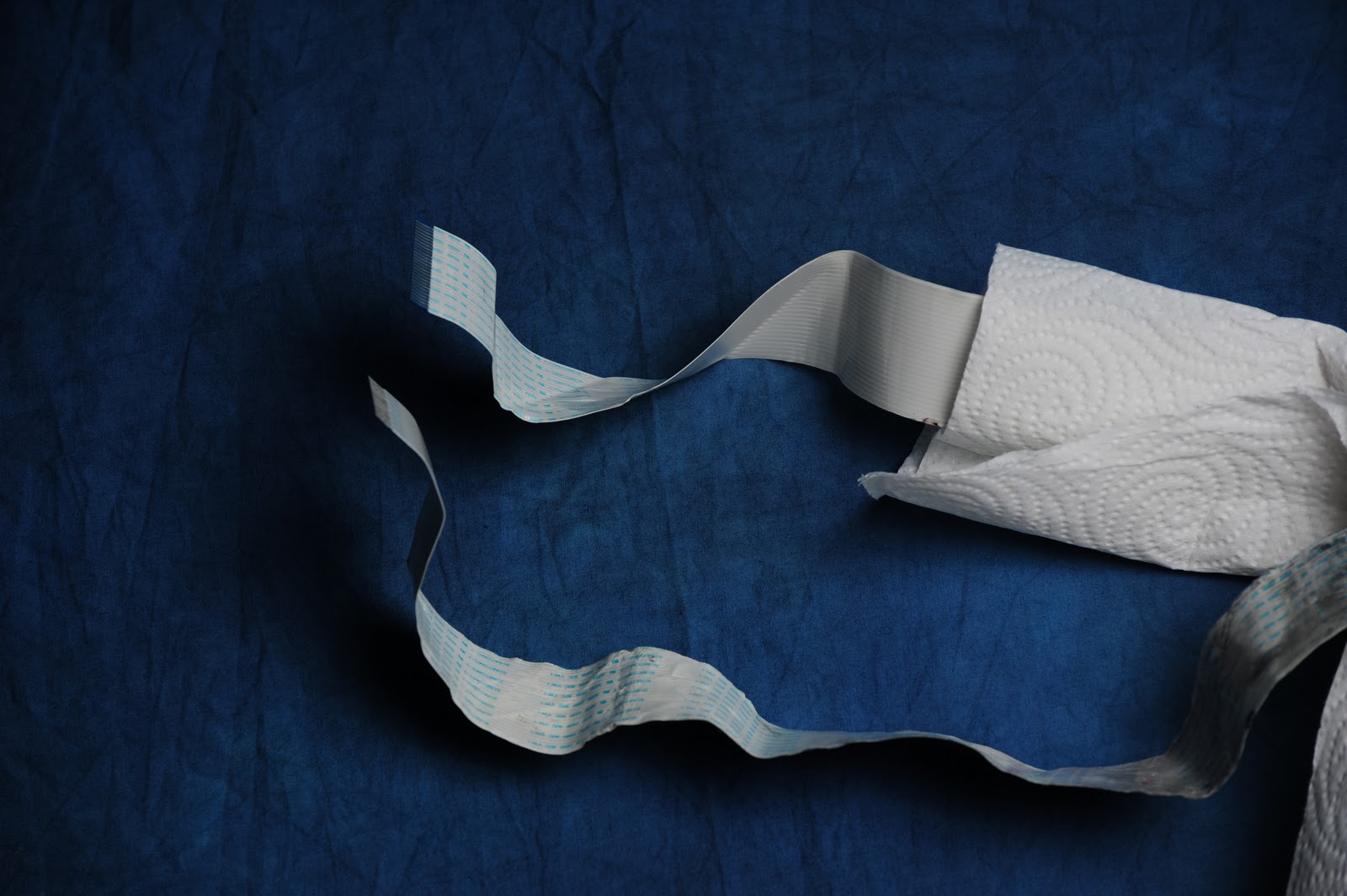
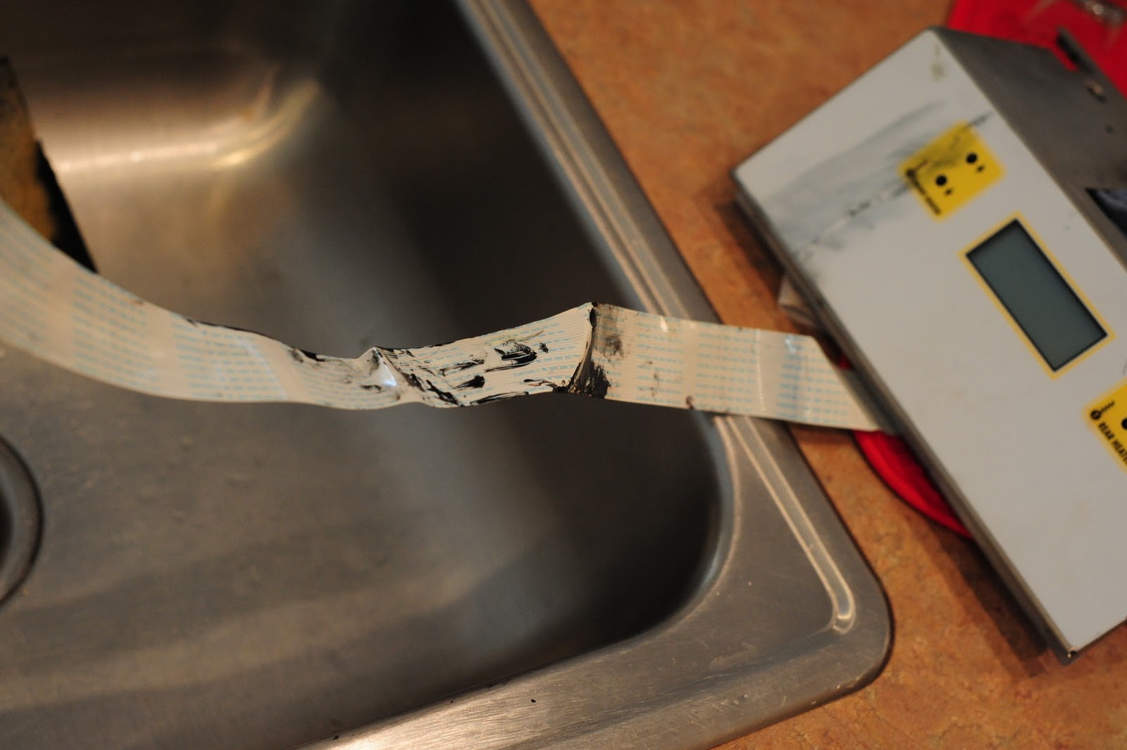
However, on this cable, the one coming from the main control panel, going to the electronics enclosure, the damage is apparent. The cable has been pinched by someone who rebuilt the printer, and at the same time, the solvent worked to soften and strip the plastic insulation from the lines. The bare wire from the ribbon cable is visible. I will need to replace this cable as it is unusable in it's current state.
This is the lid of the electronics enclosure, also covered in ink. Luckily, it does not appear that any of the ink got down inside the electronics, which is thankful, or much more would have had to be replaced. The warning sticker has been damaged by the solvent inks.
This is the right side of the electronics enclosure. Here we can see the main power supply (beige board at the bottom), the heater control board ( board with the ribbon cable at the top) and the main control board (to the left). We removed the ribbon cables from this board.
This is the left side of the electronics enclosure. Here we can clearly see the main control board. This has memory slots (bottom), expansion slots (lower left) and the ribbon cable to the control board (top).
Moving up to the top of the unit, this is the head. In this shot, we removed the top cover (six screws, two in front, four in back), and the head dust cover. In this shot you can see the six ink lines coming in from the hoses, as well as the plastic holder that supports them. The two round objects near the bottom of the head are adjusters for head height, and there is a general adjust on the right side of the head as well. The cable coming from the left is from the paper cut solenoid which I removed.
This is the board atop the head. It contains small driver electronics to run the print heads, sheet cut solenoid, and detectors. The barely-visible strip along the back of the machine is the encoder strip, how it senses where it is along the print width.
Next up: A quick head disassembly tutorial. First, remove the ink lines from the dampers. This is done by carefully loosening the nut (should only need to do a little bit with a small pliers), and unscrewing it. Pulling gently straight upwards will detatch it from the damper. BE CAREFUL at this point, as the ink is a solvent, and the plastic piece which supports the dampers is made of ABS, a plastic which the solvent will attack, soften, and ruin. Make sure you have adequate paper towels on hand for this job, as ink will continue to drip from some lines.
Next, remove the dampers by pulling each STRAIGHT UP. You will need a bit of force for this one, but make sure not to bend it, or you run the risk of snapping off the coupler on the head. Heads are way more expensive than dampers. Make sure you put some paper towel over the damper's outlet when you pull it out, as you will squeeze it and this will squirt out ink.
We already removed the dampers and one head (and as keen eyes may see, the head cable) to take this series of pictures. To remove the head, you need to first unscrew the screw holding the head down to the plastic carriage. This can be done before or after you remove the spring, and although I did it before, I think it may be easier to use the screw to loosely hold the head in place while installing/removing the spring.
You will be left with a washer on the pad, which usually sticks there. Pull the washer out with a pair of needle nose pliers.
Next, remove the spring. I am using a pair of small needle nose pliers to compress the spring on the die-cast side to avoid possibly breaking the plastic side on the head. The die-cast metal side is also shallower, and easier to get the spring off of.
Showing the spring removed. The head is now loose and can be pulled out of the unit by lifting the base up, and gently sliding it out.
The head is now free, and can be carefully lifted out.
 |
| Epson DX2 Printer head (uses 2) |
While some people claim some success with solvent and ultrasonic cleaners, parts of the head cannot be submerged. At this point, since people have difficulty reviving heads that have been sitting a few months, while these have been sitting a few years, I will be installing new heads to save the hassle.
Here is the printer in it's current state. It's torn apart, the electronics are dropped, and it's just awaiting the solvent cleaner. I also need to find a syringe and silicone tubing, though I may just use the old tubing from the ink pump, as I am getting new tubing with the refurb kit from CMYKParts.com
I plan on looking up the ribbon cables on Mouser or Digi-key, as they are standard electronic parts and I should be able to get them from one of those companies. Barring that, I'll need to locate somewhere to get parts from.
I'll take some more pictures either tonight or tomorrow morning, and get to work on cleaning it, hopefully I'll be able to get the Butyl Carbitol tomorrow (Sherwyn-Williams' commercial/industrial store was closed today) and start flushing the system. Once I can get some solvent in the lines, that should help keep things liquid until I can get some bulk cartridges to put cleaning solution into and finish flushing the system.
I plan on ordering the refurb kit around this time next week, and hopefully can get it up and running in a few days after that. Then begins the tinkering...
If you're finding this helpful, feel free to drop me a line via the links here, or at chorca@gmail.com. Any questions about what I'm doing, or if I'm doing something terribly wrong, please let me know! This is my first time working on a large format printer, so I'm bound to make some mistakes. I'll document them whenever I can, so that you guys don't make the same ones!